I work in 3D laser scanning, and many of my jobs involve urban planning and land plots, with distances of hundreds of metres. That is where I ran into something you don't even notice in a flat: the scanner and the GNSS were not giving me the same distance.
The scanner measures at scale 1; the GNSS, in UTM
The scanner measures real distances, at scale 1, like a tape measure. I register the stations in Perspective and the cloud comes out perfect.
To georeference it, I measure a few points with the GNSS and, at those same spots, I take precision points with the scanner, as Perspective calls them. The GNSS gives me those coordinates in UTM, the grid used by the cadastre and the mapping.
But UTM is the Earth flattened onto a map, and on it distances change slightly. The amount is given by the combined scale factor, which depends on where you are within the UTM zone and on the elevation.

The GNSS also has its own margin: in RTK, 1 to 4 cm horizontally, depending on the receiver and the network. That is why in a flat the scale goes unnoticed (4 mm over 10 m), while along a 500 m street it doesn't (19 cm). For areas, the effect doubles: a hectare measures almost 8 m² less in UTM.
My question: scale 1 or UTM?
If I give Perspective the points in UTM, the cloud doesn't quite fit: on that 500 m street, the 19 cm get spread out as error among the points, about 10 cm at each end with the best fit. That is far more than the GNSS margin, and Perspective, with its default tolerance, flags it in orange. No wonder its help asks for the points in ground coordinates, with a scale factor of 1. And the Business Center help explains why: the scan is at ground scale and the points are at grid scale.
So I kept asking myself: do I convert the points to scale 1, so they match the scanner, or leave them in UTM? And is it worth the trouble?
What Miguel explained to me
I asked Miguel Espinoza, from the support and training department at Al-Top, and this is how he sorted it out:
- Work out the ground factor on site. Trimble Access calculates it from the position and elevation of a point on the site, and I scale from that point. That way the GNSS points come out at scale 1 and match the scanner.
- That factor is valid within about 3 km. I checked it in Mataró: 3 km away it changes by less than 0.4 mm per 100 m. What moves it most is elevation: a 100 m difference, 1.6 mm per 100 m.
- Export the points in both UTM and ground coordinates, to keep control.
- To join the scan with the mapping and the cadastre, UTM.
- And try it both ways, depending on what each job needs.

Is it worth it? In a flat, you won't notice the scale. In urban planning and on large plots, you will.
Joining the scan with the cadastre
Careful: ground coordinates are not UTM. The way I calculate them, they match the UTM ones at the site point and drift apart as you move away. In Mataró, 19 cm at half a kilometre, 39 cm at one and 1.16 m at three.

The cadastre and the mapping and orthophoto of the ICGC (Catalonia's official mapping agency) are in UTM, so to join the cloud with them, it has to end up in UTM. Business Center does this when it georeferences the cloud with the points in UTM: it scales the cloud to the grid.
What I do now
- I keep the whole receiver job. With the original coordinates, everything can be redone.
- I note the factor and the point used to scale the ground coordinates.
- Before delivering, I load the points into CAD, in UTM, alongside the cadastre or the orthophoto, and check that they fit.
Thank you, Miguel
Miguel explains the scale factor with very clear infographics in his LinkedIn series (in Spanish). I have redone his calculations and they add up:
- “UTM vs. Escala 1: una diferencia que en obra importa”, 1 Aug 2026
- “¿Por qué en una obra la distancia UTM coincide prácticamente con la de terreno… y en otra no?”, 11 Aug 2026
- “Madrid: cuando casi 5 cm en 100 m sí importan”, 18 Aug 2026
- “Tu modelo BIM está a escala 1:1… ¿pero tus coordenadas de replanteo están en cuadrícula UTM?”, 25 Aug 2026
- “¿Qué pasa cuando un modelo BIM o un DXF no coincide con el sistema de coordenadas del trabajo?”, 8 Sep 2026
- “Coordenadas compartidas: conectando el modelo BIM con la realidad”, 15 Sep 2026
- “Meridiano de Greenwich (0°): ¿UTM 30N o UTM 31N?”, 22 Sep 2026
If you need a georeferenced point cloud for your project, tell us about the case. Request information.
Sources, consulted on 23 September 2026:
- Trimble: georeferencing in Perspective; georeferencing scans in Business Center; clouds at ground and grid scale; ground coordinate system in Trimble Access; R12i receiver user guide, p. 88: network RTK, 8 mm + 0.5 ppm horizontal.
- ICGC: CatNet network (in Catalan), RTK of 2 to 4 cm horizontal; local topographic reference, in “the official one in Catalonia (ETRS89 UTM 31 North)”, and local orthophoto, in the same system.
- BOE-A-2015-11655, Spain's Official State Gazette: cadastral mapping in ETRS89 with the UTM projection.
- NOAA, Manual NOS NGS 5, pp. 48-49: the combined factor is the product of the projection factor and the elevation factor, and areas are corrected with its square.
- My own calculations with the formulas of the USGS map projections manual and the PROJ library on EPSG:25831, using Mataró's position and altitude from Idescat and the EGM2008 geoid height.
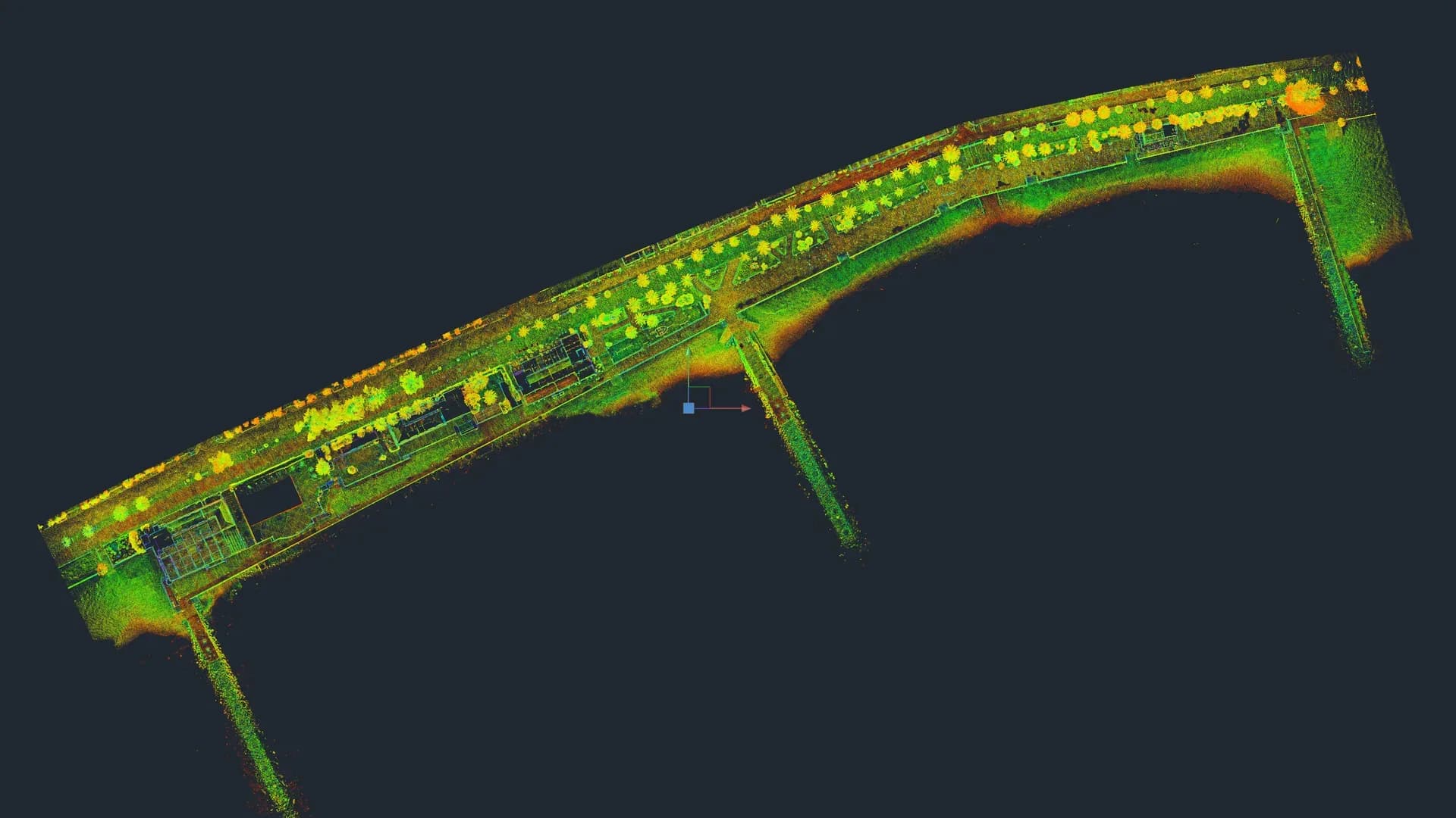
Cover image: Registra3D point cloud in Sitges.


